

UnMapper recreates a physical LED rig on the screens you actually have, and plays the real show onto it. It reads a Resolume Arena Advanced Output — the same slice map driving the real wall — receives Resolume’s outputs over NDI, and composites them onto a virtual reconstruction of the rig.
Two views of one stage, and they are not alternatives:
- Emulation — the whole rig recreated flat, one canvas pixel per LED. Each connected display shows a cropped region, so a grid of monitors becomes the wall.
- Previz — the same panels at their positions in 3D, through a camera.
An 11-panel rig in the previz view, rendered by unmapper render --previz — the same stage the
window further down is editing. Both views are fed by the same slice map and the same frames, so
what you see in one is what the other is showing.
Before you rely on this: the pipeline is built and verified end to end on real hardware — a real Arena 7.27 file, a live NDI sender at 50 fps, a real GPU — with the render paths checked by pixel readback rather than by eye.
What that does not cover: it has never run on a real LED wall or in a venue, several GUI widgets are unexercised, and there is no Syphon or Spout publishing, so NDI is the only way out.
Built with AI assistance.
The workflow
The GUI is the intended way in:
cargo run -p unmapper-gui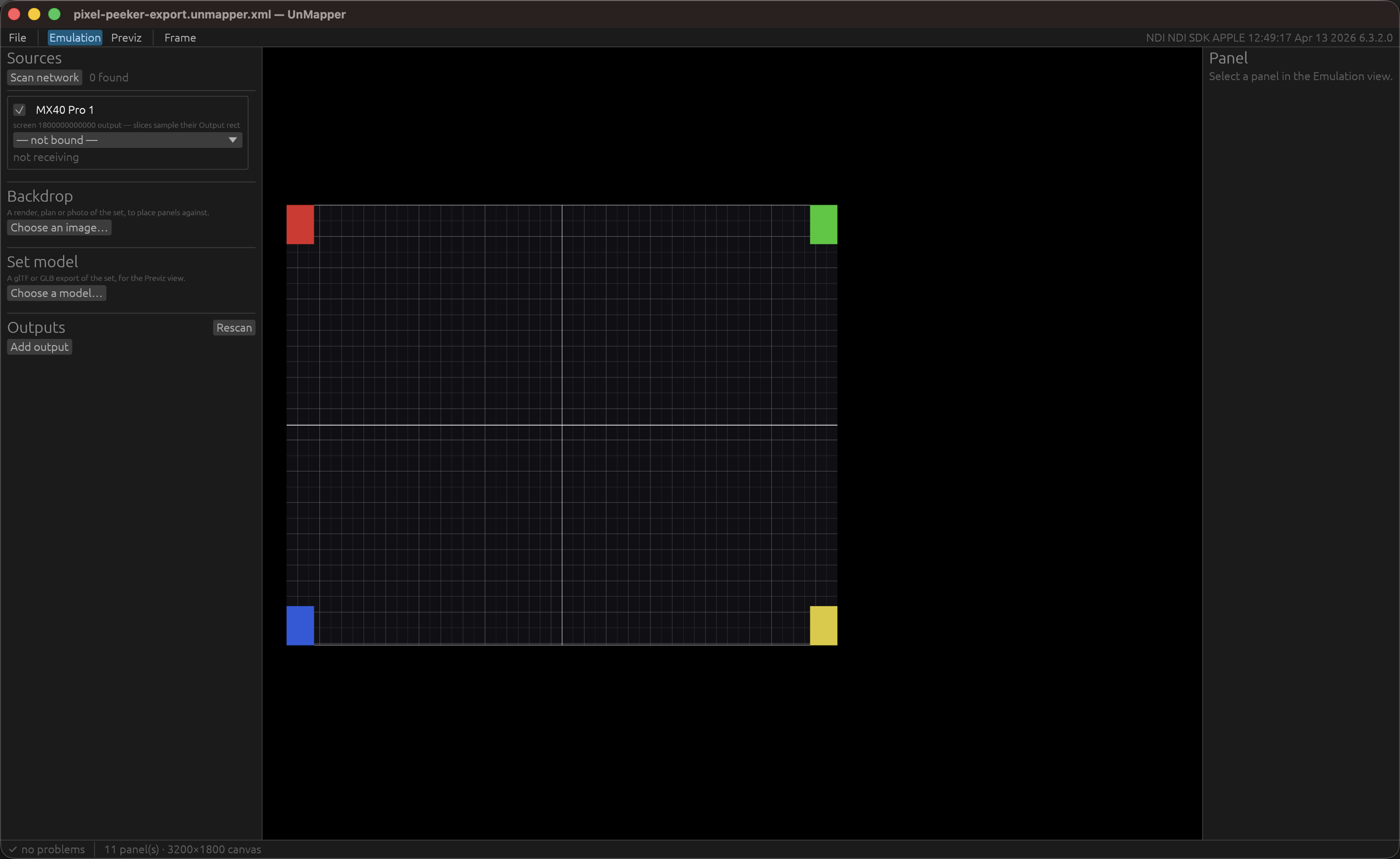
An 11-panel rig imported straight from a Resolume Advanced Output, with every source defaulted to the built-in test pattern — no Resolume and no NDI sender involved. The source reads “not bound / not receiving”, which is what an offline layout session looks like.
- Import the Resolume Advanced Output file.
- Pick an NDI source for each Resolume output.
- Drag the panels into the shape of your rig.
- Save the stage.
It also opens a stage directly:
cargo run -p unmapper-gui -- rig.unmapper.xmlEverything is available headlessly too — sources, import, bind, check, render:
cargo run -p unmapper-app -- sources
cargo run -p unmapper-app -- import "AdvancedOutput.xml" -o rig.unmapper.xml
cargo run -p unmapper-app -- bind rig.unmapper.xml --source 0 --ndi "STUDIO (Arena - Screen 1)"
cargo run -p unmapper-app -- render rig.unmapper.xml -o wall.png
cargo run -p unmapper-app -- render rig.unmapper.xml --previz -o previz.png --size 1280x720
The one thing to get right
There are five coordinate spaces, and mixing two of them up is the difference between a correct wall and a plausible-looking wrong one:
| Space | Units | Holds |
|---|---|---|
| Composition | px | Resolume’s composition raster. A slice’s input quad. |
| Screen raster | px | One Resolume output. A slice’s output quad. |
| Virtual raster | px | UnMapper’s emulation canvas — the whole rig, flat. A panel’s layout. |
| Stage | metres | The physical set, Y up. A panel’s placement. |
| Display | px | A connected monitor. An output’s region crops the canvas into one. |
A slice’s pixels live in two places, and which one to sample depends entirely on what the sender is sending.
- Resolume sending its whole composition → sample the slice’s
inputquad.- Resolume sending one feed per screen (the usual show configuration) → that feed already has the slicing applied, so sample the
outputquad.
SourceSpacerecords which. Get it wrong and everything still renders — just wrongly.
Working with nothing plugged in
A source does not have to be NDI. Two offline kinds exist so a rig can be laid out and checked with no Resolume, no network and often no venue:
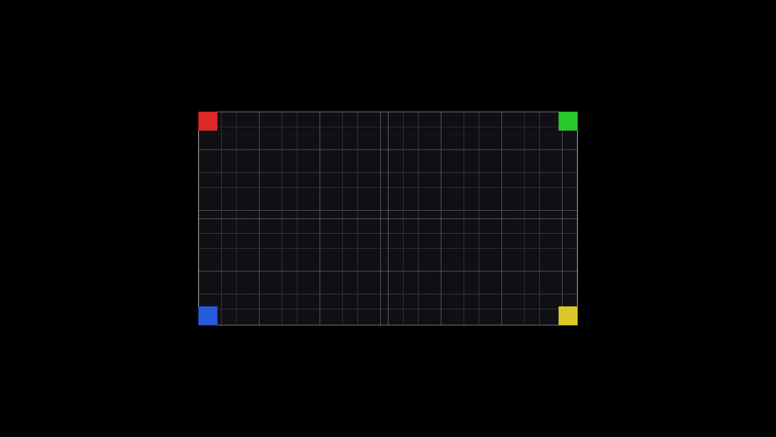
- Test pattern — a grid with four differently-coloured corners and a centre cross, sized to whatever the slice map says the screen is. Because the corners differ, a slice that is flipped, rotated or sampling the wrong region is obvious at a glance rather than plausible-looking.
- Still — any image, for laying a rig out against real artwork.
The test pattern is a geometry aid, not a colour reference. Use test-card for colour.
Describing the set
Two ways, and they are not alternatives — an operator with both should not have to choose.
A 2D mockup — a render, plan or photo of the display surface, sitting behind the panels on the emulation canvas so they can be dragged onto the places they occupy in it.
It is an editing aid and never content. The viewport draws it; the canvas that outputs crop from does not. Fade it with the opacity slider so panels stay readable over a busy render.
A 3D set model — glTF or GLB, from Blender, Cinema 4D, SketchUp or anything else. Only geometry is read; materials, cameras and animation are ignored, because this is context for judging where the walls sit, not a render. Nested node transforms are baked at load, so a truss rotated inside a rig group arrives where the file says it is.
CAD is usually in millimetres — there is a one-click mm→m button for exactly that.
Outputs
The canvas is rendered once per frame at full resolution; every output then blits the region it stands in for. Ten monitors cost one render and ten blits, and none of them can disagree about which frame they are showing.
New outputs are created windowed, not fullscreen — a fullscreen window that opens on the wrong monitor is unpleasant to get rid of. Tick the box once it looks right.
Closing an output window disables that output rather than quitting the app.
The crop is sampled nearest, so a region that is not the monitor’s own size looks blocky rather than being quietly interpolated into something plausible. That is deliberate: blocky tells you the geometry is wrong, smooth hides it.
NDI output publishes a canvas region, or the previz camera, as an NDI source. There is no Syphon or Spout — NDI is the only way out.
The stage file
A stage saves as XML you can read, diff and hand-edit, and the round trip is lossless. That makes a stage reviewable in a pull request and repairable in a text editor at 2am, which is worth more than a binary format’s convenience.
Troubleshooting
| Symptom | Cause |
|---|---|
| Wall renders but the content is wrong within each panel | Almost always the input/output quad question — check SourceSpace against what Resolume is actually sending. |
| A panel is flipped or rotated | Use a test-pattern source: the four differently-coloured corners make it obvious immediately. |
| Output looks blocky | The crop region is not the monitor’s own size. That is nearest sampling telling you so, on purpose. |
| Fullscreen window on the wrong monitor | New outputs start windowed for this reason — place it, then tick fullscreen. |
| Closing an output window seemed to do nothing | It disabled that output. The app keeps running. |
| The backdrop appears in the viewport but not on the output | Correct — it is an editing aid and never reaches an output. |
| A 3D model arrives enormous or microscopic | CAD is usually in millimetres. Use the mm→m button. |
| Model imported with no materials | Only geometry is read, deliberately. |
| Looking for Syphon or Spout | Not built. Use the NDI output. |
See also
- README — the status table, the five coordinate spaces and the stage-file schema