

Hardware · Discipline
RF & Wireless
Getting a receive antenna away from the rack without spending the link budget on cable.
Radio mic problems are hardly ever about the radio. They're about where the antenna is, what's between it and the receiver, and how much of the system's sensitivity got given away in a coax run down the side of a stage.
There's one board family here so far, and it's the physical-layer half of work that already exists as software. The coordination, monitoring and licensing tools are on the software side, and they all assume the antenna is somewhere useful. This is how it gets there.
1 board · none fabricated yet
RF & wireless · Antenna pair over one Cat cable
UHF Pair Extender
Front-end board placed · routing next
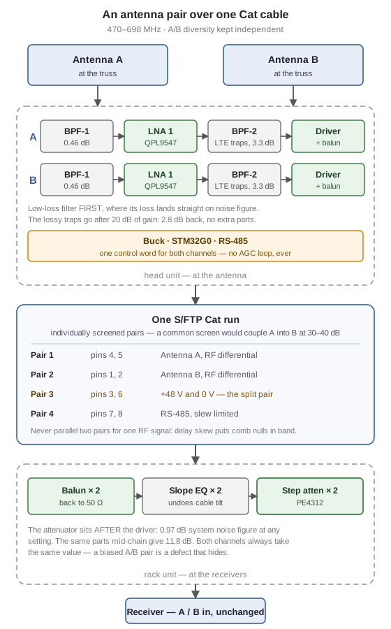
Remotes a wireless-mic receive antenna pair over a single shielded Cat cable. Filtering, gain and line drivers at the antenna end; balun, slope equalisation and a matched step attenuator pair at the rack end. 470-698 MHz, A/B diversity preserved, one cable instead of two coax runs down the side of a stage.
- Diversity stays diversityEach antenna gets its own individually screened pair. With a single overall screen, pair-to-pair crosstalk at 500 MHz is 30-40 dB, which couples antenna A into B and destroys the independence the receiver's diversity logic depends on, and never tells you.
- Noise figure comes first0.97 dB system noise figure at any attenuator setting, because the step attenuator sits after the line driver rather than mid-chain. The same parts mid-chain give 11.8 dB.
- The preselector is split on purposeLow-loss filtering before the first LNA, where its 0.46 dB lands directly on noise figure; the lossy LTE traps after 20 dB of gain, where 3.3 dB costs a hundredth as much. Worth 2.8 dB of sensitivity for no extra parts.
- No AGC, everReceivers derive squelch thresholds and diversity decisions from absolute RF level. Gain is measured once at commissioning and then frozen. A running loop that holds a target level is a defect here, not a feature.
- Power gets its own pairWideband UHF transformers rate around 30 mA and the head needs roughly 200 mA, so the DC feed rides the one pair that's split at the connector, which makes it no use for signal anyway. Never parallel two pairs for one RF signal: cable delay skew puts comb nulls inside the passband.
Where it stands
Three boards, and the one being built first isn't a product. The front-end characterisation board is a single-channel test board that exists to decide whether either production board works, because it can be measured with a VNA and one receiver. Its schematic is ERC-clean and all 43 footprints are placed, but it isn't routed and nothing has been fabricated. The head unit's schematics are roughly 80% drawn; the rack unit is an empty project. Every figure quoted above is a budget computed from datasheet numbers, not a measurement, and the first board is there to find out which of them are true.
- Band
- 470-698 MHz, A/B diversity
- Cable
- One S/FTP Cat run: 2 RF pairs, 1 DC, 1 RS-485
- Front end
- Split preselector either side of the first LNA
- Gain block
- QPL9547 LNA, TCM2-33WX+ balun
- Level control
- PE4312 step attenuator, both channels one control word
- Boards
- Head, rack, and a front-end characterisation board
- Stack-up
- 4-layer, impedance controlled, 50 ohm microstrip
- Repo
- Private
Where the sensitivity goes
Three decisions in a remote antenna head account for almost all of its performance, and all three are counter-intuitive enough to be worth spelling out. Loss before the first amplifier lands directly on noise figure, so the low-loss preselector goes first and the lossy LTE traps go after 20 dB of gain, where they cost a hundredth as much. That's worth 2.8 dB of sensitivity for no extra parts. The step attenuator goes after the driver, not mid-chain: same parts, 0.97 dB system noise figure instead of 11.8 dB.
The third is something it doesn't have: no AGC, ever. Receivers derive squelch thresholds and diversity decisions from absolute RF level, so gain is measured once at commissioning and then frozen. A loop that holds a target level behind your back is a defect here, and it's the kind of defect that turns up as an intermittent dropout three weeks later.
Diversity has to stay diverse
Two antennas sharing one cable is only worth doing if the two paths stay independent. With a single overall screen, pair-to-pair crosstalk at 500 MHz is 30–40 dB, which couples antenna A into antenna B and destroys the independence the receiver's diversity logic is built on, without ever letting on. So the cable spec is individually screened pairs, and that's a requirement rather than a recommendation.
The related trap is paralleling two pairs to carry one signal. Pairs are twisted at different rates on purpose, so they differ in electrical length, and the allowed skew puts comb nulls inside the passband at UHF. Skew is usually a data-cable worry; this is it turning up in an analogue shortcut.
Related, elsewhere on the site
The whole bench
This is only one corner of it
The hardware index has every board on one page, and you can filter it by discipline: lighting nodes, audio boxes, video processing, the physical layer under all of it and the RF work on top.