

Hardware · Discipline
Networking & Infrastructure
The physical layer under everything else: distance, power, screens and connectors.
A big event network is mostly a cabling problem wearing a networking badge. The protocols are settled. What decides whether the show works is how far a run can go, what happens to power along the way, and whether the screen at one end is still a screen at the other.
These are the boards for problems that no amount of configuration fixes. A hundred metres is a hundred metres. A cable screen tied to a chassis at both ends is a ground loop, whatever the switch thinks.
2 boards · none fabricated yet
Audio · 1U passive Cat-to-XLR fan-out
etherCON Stagebox Fan-out
Design complete · gerbers generated, nothing fabricated
A passive 1U fan-out: four etherCON in, sixteen XLR out on flying tails, four balanced channels per Cat run. The signal path is fully passive and DC-coupled, so phantom power crosses it untouched. Each unit is self-contained, so 32 channels is two of them and 48 is three, instead of one crowded chassis nobody can rack next to anything.
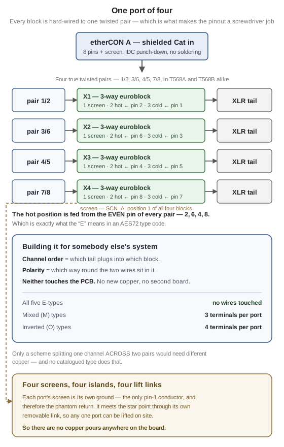
- One board, every system on the marketFour balanced channels on four twisted pairs is settled. Which channel lands on which pair, and which end of it is hot, isn't: there are nine catalogued schemes and they're mutually incompatible. Here every XLR lands on its own three-way terminal block, hard-wired to exactly one pair, so channel order is which tail you plug in where and polarity is which way round two wires sit. Both are screwdriver jobs, and neither touches the PCB.
- Five of the nine need no work at allThe hot position is fed from the even pin of every pair, which is what the E in an AES72 type code means. So every E-type variant is just relabelling. The mixed types need three terminals swapping per port and the fully inverted ones four: about a minute with a screwdriver.
- Four screen islands, kept apart on purposeEach Cat run's screen is its own ground, meeting the star point only through its own lift link. There are no copper pours anywhere on this board, because one continuous fill would short all four together and still pass every continuity test you'd think to run.
- A wrong pinout can't scrap a boardThe map is in copper, but every degree of freedom that map fixes is undone at a terminal block. A mis-transcribed pinout costs you a screwdriver rather than a fab run, which matters, because half the published maps in this corner of the industry disagree with each other.
- Nothing to alignThe etherCONs are chassis-mounted and reach the board on a flying link, so panel-to-PCB registration (normally the thing that ruins a first build) doesn't come into it.
Adapting it to somebody else's stagebox
The default build is wired to one convention. Every other system on the market is the same board with the tails moved, and for five of the nine catalogued types not even that. Here's the whole build sheet:
| System | AES72 type | To build that variant |
|---|---|---|
| the sssnake Cat Snake | 1E | Nothing - this is the default build |
| Neutrik AES72 stagebox | 4E | Nothing but relabelling: same wires, different tail into each block |
| Whirlwind Catdusa | 1M | Three terminals reversed per port |
| Radial Catapult | no AES72 type | Three terminals reversed per port, channel order reversed |
| SoundTools CAT Box | 2O | All four terminals reversed per port |
Radial matches none of the nine because they number channels from the far end of the connector: it's Type 1M with the channel order reversed. Only a scheme that split one channel across two pairs would need different copper, and no catalogued type does that.
The nine types, every manufacturer's map, and what happens when you mix two systems
Where it stands
Design complete, DRC clean, fabrication package generated, and nothing has been made. The big open risk is the pinout itself. The manufacturer whose snakes the default build is meant to meet doesn't publish its convention anywhere, so the map is community-sourced: it passes the twisted-pair sanity check, but it hasn't been metered. Put a meter on a real Cat snake before you make up sixteen tails. A wrong map can't waste a board (it's a screwdriver fix), but it can waste an evening. The other hard requirement is the cable: the screen is the only pin-1 conductor, so on unshielded Cat, phantom power can't work at all.
- Format
- 1U, 4x etherCON in, 16x XLR out
- Channels
- 4 balanced per Cat run, 16 per unit
- Signal path
- Passive, DC-coupled - phantom passes through
- As built
- AES72 Type 1E; all nine types by rewiring
- Board
- 380 x 72 mm, 2-layer, all through-hole
- Grounding
- 4 isolated screen islands, one lift link each
- Cable
- Shielded Cat - mandatory, not advisory
- Repo
- Private
Infrastructure · Inline 10GBASE-T regenerator
etherCON 10G PoE Repeater
Feasibility closed · schematic capture
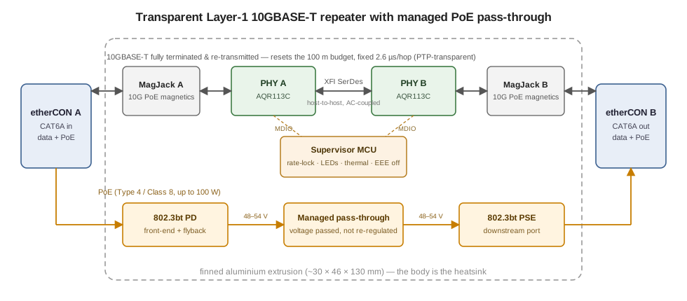
An inline, fanless Layer-1 10GBASE-T repeater with managed pass-through PoE, built into a shell the size of a Neutrik NE8FF feedthrough. Drop one in mid-run and it resets the 100 m cabling budget, so a cat6a run can be extended past spec.
- Not a booster10GBASE-T can't be analogue-amplified. The link is fully terminated in a PHY and re-transmitted, which resets the distance budget and hands the far end a fresh eye.
- Invisible to the networkNo MAC, no switch fabric and no store-and-forward, so it's transparent to L2/L3 and, above all, to PTP. It looks like a slightly longer cable.
- PoE passes through, managedAn 802.3bt PD front-end feeding an 802.3bt PSE, so power crosses the joint under supervision rather than by accident.
- Fits the shell it has to fitTwo AQR113C PHYs host-to-host over fixed 10G XFI on a ~119 mm board, inside a finned extrusion the size of the coupler it replaces.
Where it stands
Electronics feasibility is closed with margin and the thermal budget is written down. The KiCad project has both PHY sheets wired, but the risk that's left is mechanical fit, and no board has been made.
- PHYs
- 2x Marvell AQR113C, host-to-host XFI
- Rate
- 10GBASE-T, fixed 10G
- Magnetics
- Bel 10G PoE MagJack
- Power
- 802.3bt PD in, 802.3bt PSE out
- Board
- ~119 mm, NE8FF-size finned extrusion
- Repo
- Private
etherCON Stagebox Fan-out is also on Audio
Two limits that keep coming back
The first is distance. 802.3 gives you 100 m and the venue gives you 140, and there's no analogue answer, because 10GBASE-T can't be amplified. The only proper fix is to terminate the link in a PHY and re-transmit it, which resets the budget and hands the far end a fresh eye. Doing that without turning into a switch is the interesting part: no MAC and no store-and-forward means the unit stays transparent to L2, L3 and, above all, PTP. It looks like a slightly longer cable.
The second is that copper carries power and ground as well as data, and both of those have opinions. Power crossing a joint mid-cable has to be supervised rather than passed along by accident, and a screen has to be bonded on purpose (once, at one end) or the analogue system running beside it hums.
Why so little of this is downloadable
Because infrastructure is specific to the job. What's worth keeping from a multi-room build is a topology, an addressing plan and a set of decisions about what shares a VLAN with what, and those are documents rather than products. What's left over, the parts that are the same on every job, is physical, and that's what ends up on this page.
Neither board here has been fabricated. The repeater's electronics feasibility is closed with margin and its thermal budget is written down. What's left is mechanical, and that's the one part you can't close on paper.
Related, elsewhere on the site
The whole bench
This is only one corner of it
The hardware index has every board on one page, and you can filter it by discipline: lighting nodes, audio boxes, video processing, the physical layer under all of it and the RF work on top.