
Hardware
Boards for jobs nobody makes a box for
Eight open designs, and every one of them started on a gig: a DMX node that daisy-chains on one Cat5, a bridge that lets a control app you already own drive amplifiers it was never sold to talk to, a stage fan-out you rewire to any manufacturer's Cat snake with a screwdriver, a wireless-mic antenna pair sent down a single Cat cable, a video mainframe, a mixing console computed in FPGA fabric, a coupler that stretches a cat6a run past spec, and a network video decoder that tells you its own IP address.
Where they've got to: all designed, some simulated. One of them, CANary, has now been built, and board #1 is powered and running on a bench. The rest haven't been fabricated. Each board says what has and hasn't been run on real hardware, because I'd rather you heard it from me.
Or read a discipline in full: AudioVideoLightingNetworking & InfrastructureRF & Wireless
Audio · IP and USB to CAN bus converter
CANary
Rev A built · board #1 powered, flashed and passing its self-test
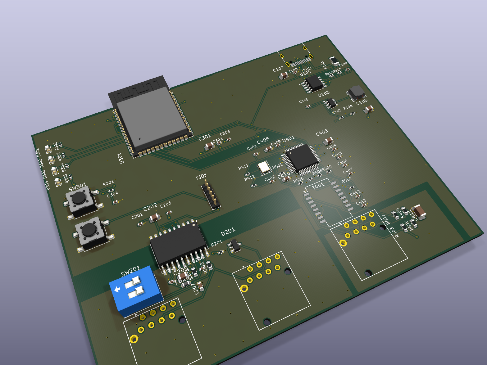
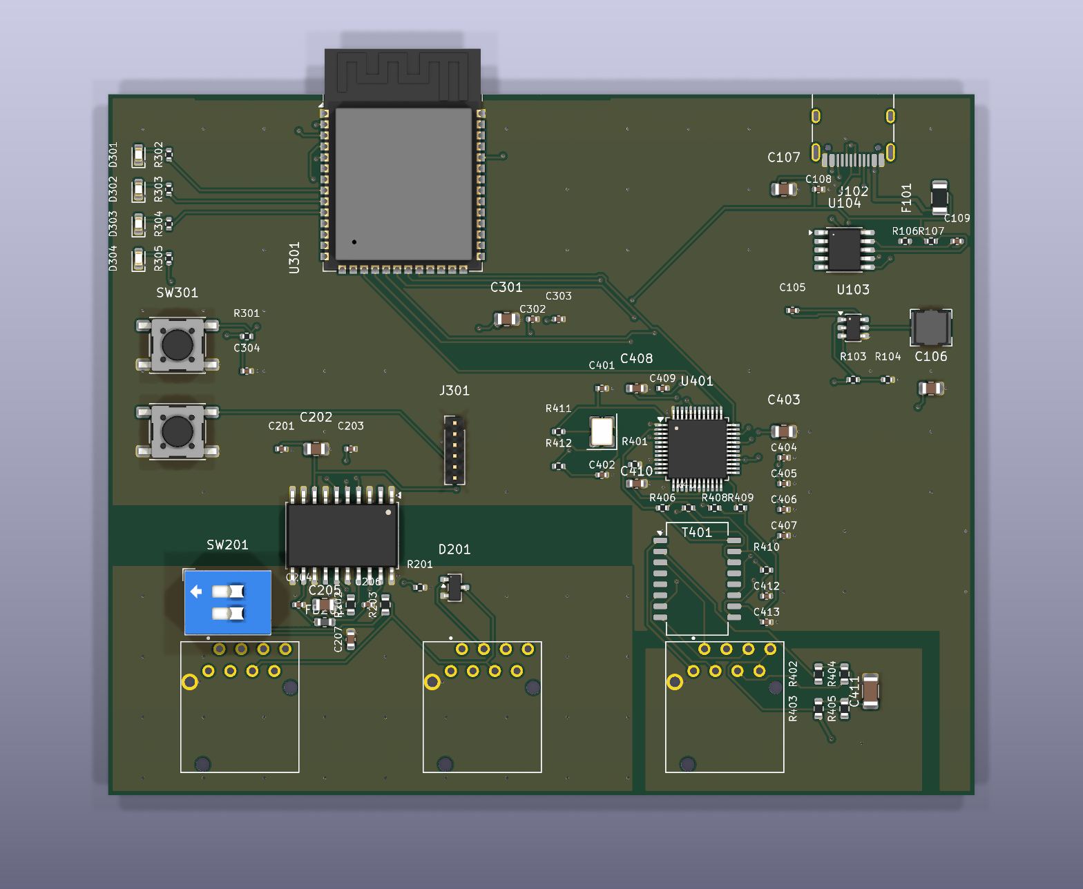
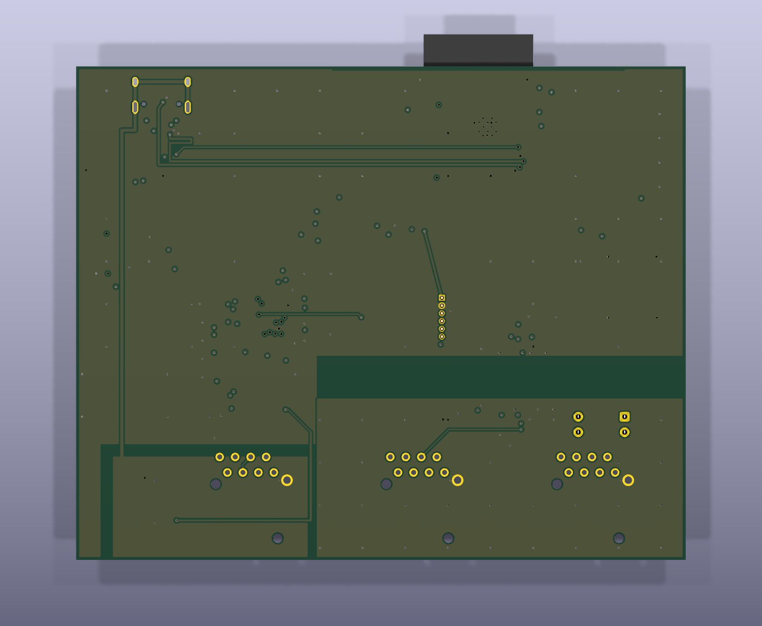
An IP and USB to CAN bus converter for use with the d&b amplifier ecosystem. It puts amplifiers that only speak CAN onto the network, so the control software you already run can discover and drive them through hardware you can build yourself.
- Transparent bridgeNo interpretation and no extra protocol layer. The gateway is invisible to the control application, which is what it's for.
- Running on real hardwareBoard #1 came up on the first plug-in. Ethernet, the isolated CAN transceiver and the whole network protocol all answer on the bench.
- Galvanically isolatedThe CAN side sits across a 7 mm barrier on an ADM3053 with its own supply, so an amplifier rack and a laptop never share a ground through this box.
- Standard partsESP32-S3, W5500 Ethernet, ADM3053 isolated CAN. Nothing exotic, nothing unobtainable. 45 of the 50 BOM lines carry a part checked against live distributor stock, and the other five are the hand-soldered connectors.
- Bench test rigA self-test image the board runs on itself, a host-side acceptance script, and a written bring-up procedure with generated probe-point drawings.
Where it stands
Boards exist and one of them works. Board #1 enumerated over USB first time, passed its own self-test six for six, took a DHCP lease and answered a host-side acceptance run of nineteen network checks. The control application discovers it and lists it. On 26 September 2026 the USB network build met its first laptop: it now hands the laptop an address, serves its settings page, and passes the same nineteen checks down the cable. What that doesn't cover: the CAN side has only been run as a loopback through its own transceiver, never against a real amplifier bus; the bench sequence of rail and isolation-resistance measurements was skipped on this board; the indicator LEDs and the power-delivery status pin still need somebody to look at them; and the last link, the control application actually driving amplifiers through it, isn't finished. One board from the batch has been touched. Rev B is where the fixes go.
- MCU
- ESP32-S3
- Network
- W5500 Ethernet
- Bus
- ADM3053 isolated CAN, 100 kbit/s
- Isolation
- 7 mm barrier, separate CAN-side supply
- Board
- 100 x 81 mm, 4-layer
- Assembly
- 76 placements, top side only
- Power
- USB-C PD
- Role
- IP and USB to CAN bus converter
- For
- The d&b amplifier ecosystem
- Firmware
- Flashed from a browser tab with the CANary Flasher
- Repo
- Private
Audio · 1U passive Cat-to-XLR fan-out
etherCON Stagebox Fan-out
Design complete · gerbers generated, nothing fabricated
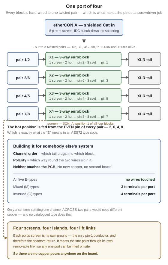
A passive 1U fan-out: four etherCON in, sixteen XLR out on flying tails, four balanced channels per Cat run. The signal path is fully passive and DC-coupled, so phantom power crosses it untouched. Each unit is self-contained, so 32 channels is two of them and 48 is three, instead of one crowded chassis nobody can rack next to anything.
- One board, every system on the marketFour balanced channels on four twisted pairs is settled. Which channel lands on which pair, and which end of it is hot, isn't: there are nine catalogued schemes and they're mutually incompatible. Here every XLR lands on its own three-way terminal block, hard-wired to exactly one pair, so channel order is which tail you plug in where and polarity is which way round two wires sit. Both are screwdriver jobs, and neither touches the PCB.
- Five of the nine need no work at allThe hot position is fed from the even pin of every pair, which is what the E in an AES72 type code means. So every E-type variant is just relabelling. The mixed types need three terminals swapping per port and the fully inverted ones four: about a minute with a screwdriver.
- Four screen islands, kept apart on purposeEach Cat run's screen is its own ground, meeting the star point only through its own lift link. There are no copper pours anywhere on this board, because one continuous fill would short all four together and still pass every continuity test you'd think to run.
- A wrong pinout can't scrap a boardThe map is in copper, but every degree of freedom that map fixes is undone at a terminal block. A mis-transcribed pinout costs you a screwdriver rather than a fab run, which matters, because half the published maps in this corner of the industry disagree with each other.
- Nothing to alignThe etherCONs are chassis-mounted and reach the board on a flying link, so panel-to-PCB registration (normally the thing that ruins a first build) doesn't come into it.
Adapting it to somebody else's stagebox
The default build is wired to one convention. Every other system on the market is the same board with the tails moved, and for five of the nine catalogued types not even that. Here's the whole build sheet:
| System | AES72 type | To build that variant |
|---|---|---|
| the sssnake Cat Snake | 1E | Nothing - this is the default build |
| Neutrik AES72 stagebox | 4E | Nothing but relabelling: same wires, different tail into each block |
| Whirlwind Catdusa | 1M | Three terminals reversed per port |
| Radial Catapult | no AES72 type | Three terminals reversed per port, channel order reversed |
| SoundTools CAT Box | 2O | All four terminals reversed per port |
Radial matches none of the nine because they number channels from the far end of the connector: it's Type 1M with the channel order reversed. Only a scheme that split one channel across two pairs would need different copper, and no catalogued type does that.
The nine types, every manufacturer's map, and what happens when you mix two systems
Where it stands
Design complete, DRC clean, fabrication package generated, and nothing has been made. The big open risk is the pinout itself. The manufacturer whose snakes the default build is meant to meet doesn't publish its convention anywhere, so the map is community-sourced: it passes the twisted-pair sanity check, but it hasn't been metered. Put a meter on a real Cat snake before you make up sixteen tails. A wrong map can't waste a board (it's a screwdriver fix), but it can waste an evening. The other hard requirement is the cable: the screen is the only pin-1 conductor, so on unshielded Cat, phantom power can't work at all.
- Format
- 1U, 4x etherCON in, 16x XLR out
- Channels
- 4 balanced per Cat run, 16 per unit
- Signal path
- Passive, DC-coupled - phantom passes through
- As built
- AES72 Type 1E; all nine types by rewiring
- Board
- 380 x 72 mm, 2-layer, all through-hole
- Grounding
- 4 isolated screen islands, one lift link each
- Cable
- Shielded Cat - mandatory, not advisory
- Repo
- Private
Audio · FPGA-native live mixing console
LOOM
DSP core bit-exact under Verilator
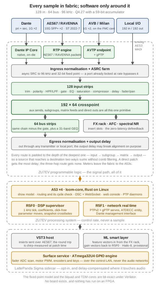
An open, FPGA-native live mixing console. 128 inputs, 64 buses, every channel strip computed in fabric at 96 kHz, speaking Dante, RAVENNA/AES67 and AVB/Milan at the same time, with an x86 sidecar for VST3 hosting and NPU-accelerated ML audio.
- Everything in fabric128 in, 64 bus, 32-bit fixed-point Q4.27 with a 59-bit accumulator. No DSP chips to run out of.
- Three AoIP stacks at onceDante native on-die, AES67/RAVENNA and AVB/Milan in the PL, all running together rather than one at a time.
- Latency-aligned routingA full 192x64 crosspoint where any input reaches any output in the same sample count, whatever the route depth.
- Checked against a modelA fixed-point Rust reference model pins the arithmetic, and the SystemVerilog is checked bit-exact against it.
- An optional smart layerML feedback prediction and noise reduction on a Hailo-8, fed feature vectors computed in fabric.
Where it stands
The fixed-point model and the biquad and TDM cores are built and verified bit-exact under Verilator. That's a long way from a console: no board exists, and nothing has run on an FPGA.
- Platform
- AMD Zynq UltraScale+ XCZU7EV (ZCU106)
- Channels
- 128 in / 64 bus @ 96 kHz
- Format
- Q4.27 fixed-point, 59-bit accumulator
- AoIP
- Dante + AES67/RAVENNA + Milan
- Local I/O
- 192 in / 192 out (analog, AES3, MADI)
- Repo
- Private
Video · Modular AV processing mainframe
OpenAVSwitch
Phase 1 design · RTL in simulation
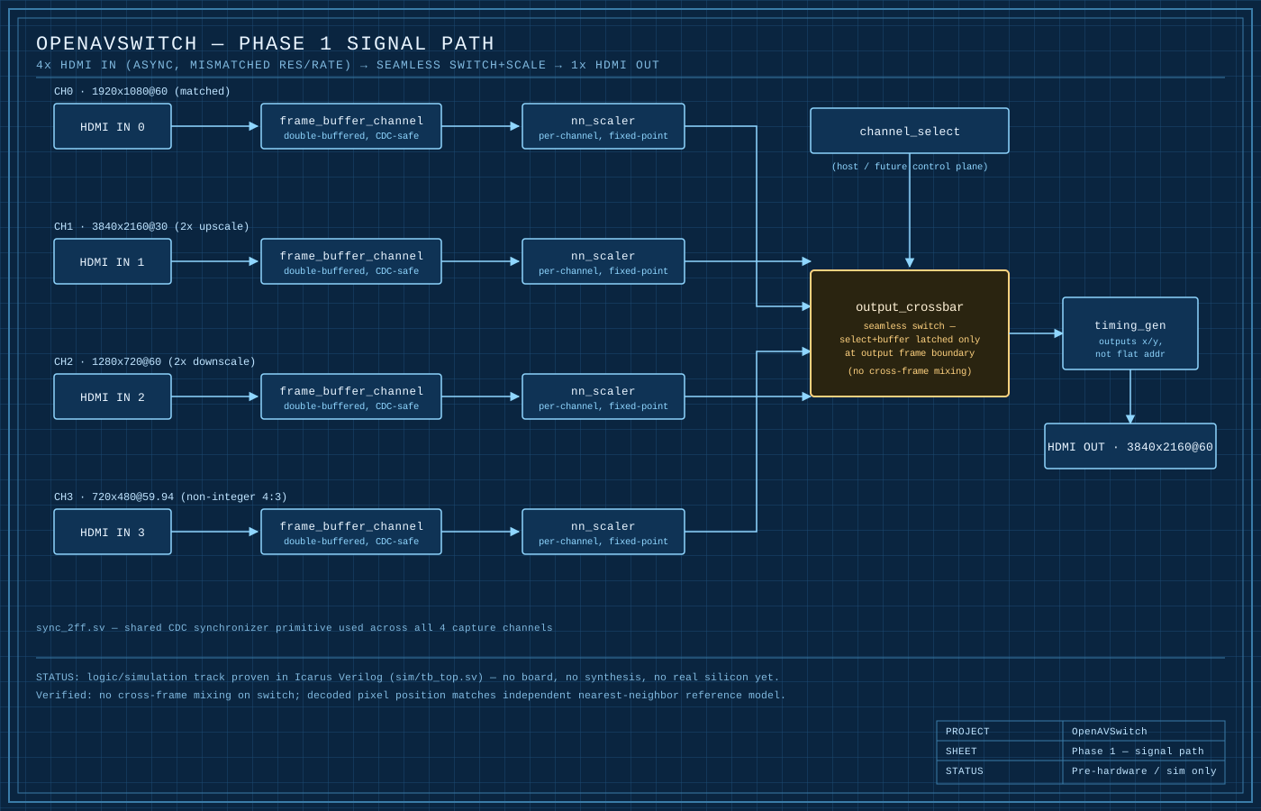
An open, modular AV processing mainframe: many simultaneous inputs, multi-layer real-time compositing and scaling, and seamless switching, built on commodity FPGA SoCs instead of closed, proprietary hardware.
- Phase 1 is small on purposeA 4-in / 1-out HDMI 4K seamless switcher. Prove the pipeline before scaling the frame.
- Compositing in fabricMulti-layer scaling and mixing on Zynq UltraScale+, not on a GPU that has to be scheduled.
- Seamless by constructionSwitching happens inside the video pipeline, so there's no black frame to hide.
- Modular frameInput, output and processing as separate cards, so the frame grows rather than being replaced.
Where it stands
Design and RTL only. None of it has been through professional design review or run on real hardware: it exists in simulation. Read the RTL with a sceptical eye before you rely on any of it.
- Platform
- Xilinx Zynq UltraScale+ SoC
- Phase 1
- 4-in / 1-out HDMI, 4K
- Class
- Large-format live video processor
- Language
- SystemVerilog
- Repo
- Private
Video · NDI and SRT decoder
PineMarten
SRT path built · NDI licensing unresolved
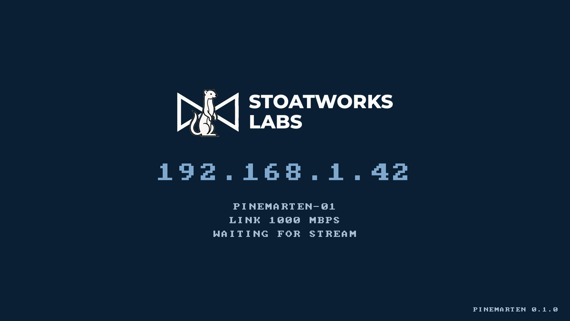
Open decoder firmware for a commodity single-board computer: a stream in over the network, a picture out of HDMI, for a fraction of what a closed appliance costs. Web UI, OSC and AES70 control, mDNS, and a boot splash that tells you the IP address of the box you're standing in front of.
- It tells you where it isFrom power-on it shows its own IP address, hostname, link speed and why it has no picture yet. A decoder that explains itself saves a walk to the truss.
- Switches without a black frameThe splash and the video live on separate hardware planes, so a stream arriving is a visibility change rather than a mode set with a blank screen in the middle of it.
- Fails over on picture, not handshakeA source is promoted when it delivers a frame, never when it merely connects. A connection carrying nothing is a failure that looks like a success.
- Hardware decode or a loud complaintSRT goes straight to the SoC's video unit. If the hardware decoder is ever missing, the firmware says so rather than quietly falling back to software and stuttering.
- One cablePower over Ethernet, or USB-C on a bench.
Where it stands
No board exists yet. The SRT receive and decode path is exercised end to end against a real stream, but in software on a development machine, and the display backend has never been run at all. Every performance figure is arithmetic from published specs, not a measurement, and the NDI decode budget in particular is an estimate with a wide error bar. Bigger than any of that: the free NDI SDK licence appears to exclude fixed-purpose Linux appliances, and that's what this is. So whether the NDI half can ship at all is an open question for the vendor, and no amount of code will settle it. SRT is unaffected.
- Platform
- Radxa ZERO 3E (Rockchip RK3566)
- Output
- 1x HDMI, 1080p60
- Transports
- SRT, NDI High Bandwidth, NDI|HX
- Control
- Web UI, OSC, AES70/OCA, mDNS
- Power
- PoE (802.3af) or USB-C
- Repo
- Private
Lighting · Art-Net / sACN to DMX512
nanODE
Board v0.4.1 · routing in progress
A PoE-powered, daisy-chainable Art-Net / sACN to 4x DMX512 node. One Cat5 in and one loop out, carrying power and data, so a run of nodes needs a single cable from the switch instead of one per box.
- 4 universes out5-pin XLR, from Art-Net 4 (including ArtSync) or sACN / E1.31.
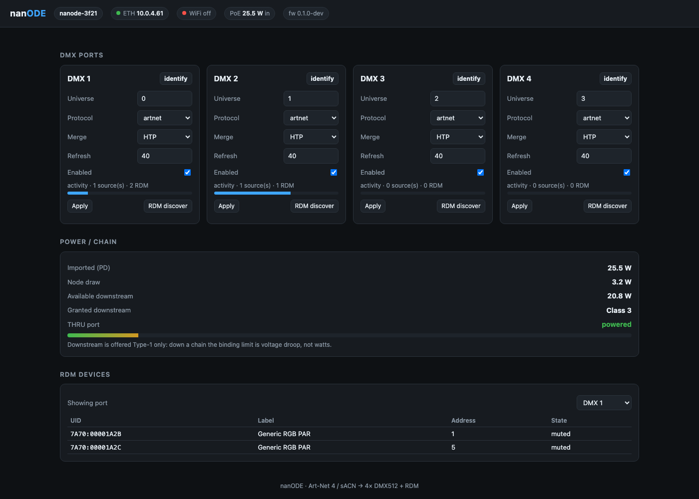
- Real RDM discoveryRuns as a background task, so the web console never blocks on it.
- Daisy-chain built inInternal 3-port switch: Cat5 in, loop out, plus the ESP32 itself.
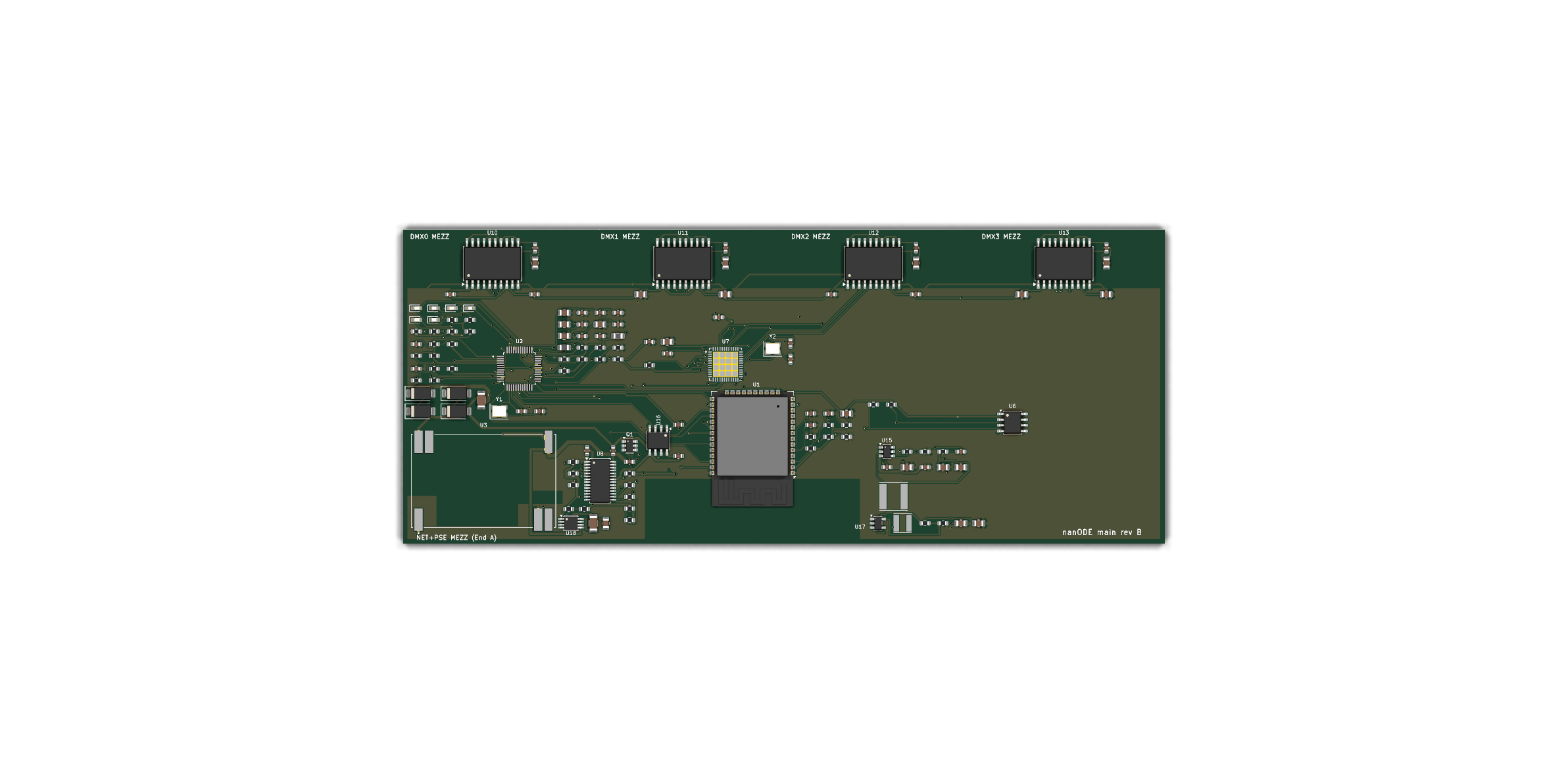
- Field-replaceable portsEvery external connector is a daughter-card. Smash an XLR on site, swap it without a soldering iron.
- Browser consoleOver WiFi or Ethernet: patch, address, and see RDM devices live.
Where it stands
The firmware builds clean against real ESP-IDF 5.5 tooling, and the REST API and RDM discovery are verified against a mock node. But it has never run on real silicon, and the board render is older than the current layout.
- MCU
- ESP32
- Network
- Internal 3-port switch, PoE
- Outputs
- 4 x DMX512 on 5-pin XLR
- Protocols
- Art-Net 4, sACN / E1.31, RDM
- Enclosure
- Aluminium extrusion, laser-cut acrylic ends
- Repo
- Private
Infrastructure · Inline 10GBASE-T regenerator
etherCON 10G PoE Repeater
Feasibility closed · schematic capture
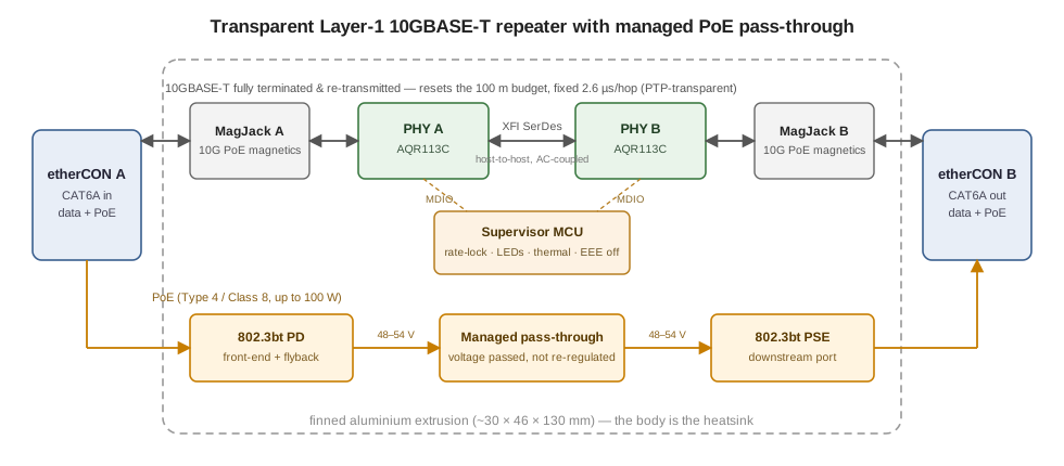
An inline, fanless Layer-1 10GBASE-T repeater with managed pass-through PoE, built into a shell the size of a Neutrik NE8FF feedthrough. Drop one in mid-run and it resets the 100 m cabling budget, so a cat6a run can be extended past spec.
- Not a booster10GBASE-T can't be analogue-amplified. The link is fully terminated in a PHY and re-transmitted, which resets the distance budget and hands the far end a fresh eye.
- Invisible to the networkNo MAC, no switch fabric and no store-and-forward, so it's transparent to L2/L3 and, above all, to PTP. It looks like a slightly longer cable.
- PoE passes through, managedAn 802.3bt PD front-end feeding an 802.3bt PSE, so power crosses the joint under supervision rather than by accident.
- Fits the shell it has to fitTwo AQR113C PHYs host-to-host over fixed 10G XFI on a ~119 mm board, inside a finned extrusion the size of the coupler it replaces.
Where it stands
Electronics feasibility is closed with margin and the thermal budget is written down. The KiCad project has both PHY sheets wired, but the risk that's left is mechanical fit, and no board has been made.
- PHYs
- 2x Marvell AQR113C, host-to-host XFI
- Rate
- 10GBASE-T, fixed 10G
- Magnetics
- Bel 10G PoE MagJack
- Power
- 802.3bt PD in, 802.3bt PSE out
- Board
- ~119 mm, NE8FF-size finned extrusion
- Repo
- Private
RF & wireless · Antenna pair over one Cat cable
UHF Pair Extender
Front-end board placed · routing next
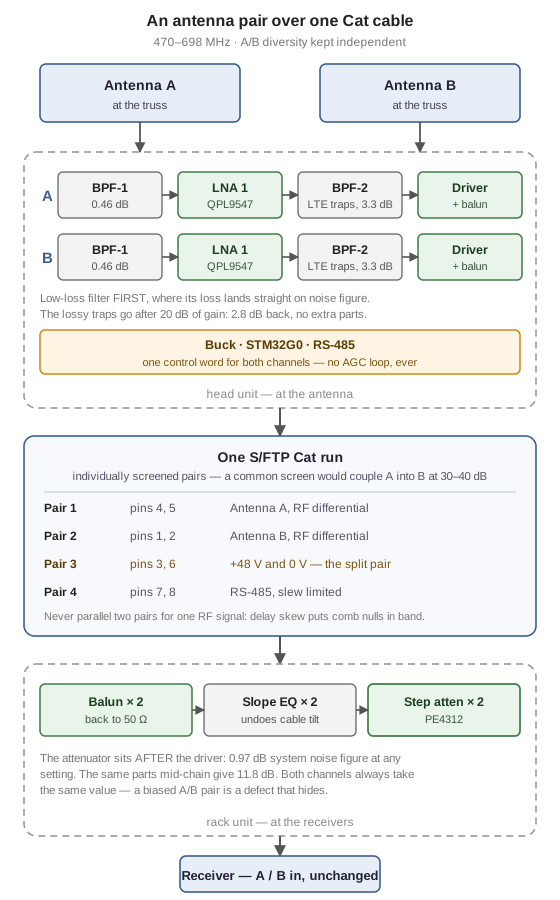
Remotes a wireless-mic receive antenna pair over a single shielded Cat cable. Filtering, gain and line drivers at the antenna end; balun, slope equalisation and a matched step attenuator pair at the rack end. 470-698 MHz, A/B diversity preserved, one cable instead of two coax runs down the side of a stage.
- Diversity stays diversityEach antenna gets its own individually screened pair. With a single overall screen, pair-to-pair crosstalk at 500 MHz is 30-40 dB, which couples antenna A into B and destroys the independence the receiver's diversity logic depends on, and never tells you.
- Noise figure comes first0.97 dB system noise figure at any attenuator setting, because the step attenuator sits after the line driver rather than mid-chain. The same parts mid-chain give 11.8 dB.
- The preselector is split on purposeLow-loss filtering before the first LNA, where its 0.46 dB lands directly on noise figure; the lossy LTE traps after 20 dB of gain, where 3.3 dB costs a hundredth as much. Worth 2.8 dB of sensitivity for no extra parts.
- No AGC, everReceivers derive squelch thresholds and diversity decisions from absolute RF level. Gain is measured once at commissioning and then frozen. A running loop that holds a target level is a defect here, not a feature.
- Power gets its own pairWideband UHF transformers rate around 30 mA and the head needs roughly 200 mA, so the DC feed rides the one pair that's split at the connector, which makes it no use for signal anyway. Never parallel two pairs for one RF signal: cable delay skew puts comb nulls inside the passband.
Where it stands
Three boards, and the one being built first isn't a product. The front-end characterisation board is a single-channel test board that exists to decide whether either production board works, because it can be measured with a VNA and one receiver. Its schematic is ERC-clean and all 43 footprints are placed, but it isn't routed and nothing has been fabricated. The head unit's schematics are roughly 80% drawn; the rack unit is an empty project. Every figure quoted above is a budget computed from datasheet numbers, not a measurement, and the first board is there to find out which of them are true.
- Band
- 470-698 MHz, A/B diversity
- Cable
- One S/FTP Cat run: 2 RF pairs, 1 DC, 1 RS-485
- Front end
- Split preselector either side of the first LNA
- Gain block
- QPL9547 LNA, TCM2-33WX+ balun
- Level control
- PE4312 step attenuator, both channels one control word
- Boards
- Head, rack, and a front-end characterisation board
- Stack-up
- 4-layer, impedance controlled, 50 ohm microstrip
- Repo
- Private
Nothing under that heading yet. .
More hardware
There's a queue behind these
A touring control surface for the desk. A custom surface for the dMix 128. An in-house PCB assembly line, so these stop being quotes from someone else. They're all at various stages of not being finished, and they'll turn up here once they're close enough to show.