Stoatworks Labs

CANary

IP and USB to CAN bus converter, for the d&b amplifier ecosystem

Prototype · rev Av0.1.0Open hardwareESP32-S3
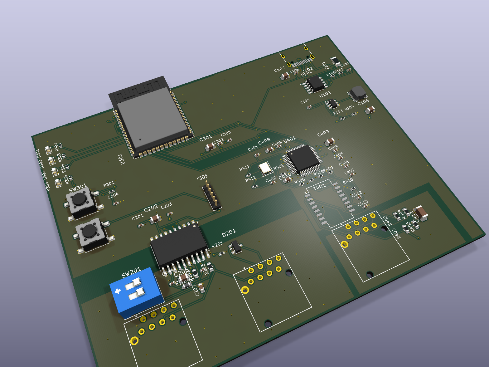
CANary rev A board, isometric render
Rev A, rendered from the routed board. The three jacks along the front edge are one network and two CAN.

What it does

A lot of amplifiers speak CAN and nothing else. The control software that drives them expects to find them on a network, and the box that bridges the two is a discontinued piece of someone else's hardware that turns up rarely and costs what rare things cost. CANary is that bridge, as an open board you can build.

It is deliberately a transparent bridge and nothing more. It does not interpret a single amplifier parameter, adds no protocol of its own, and holds no state about what is on the bus. The control application should not be able to tell it apart from the hardware it stands in for, and if it ever can, that is a bug rather than a feature.

The same USB-C cable that powers it can also make it a network adapter: plug it into a laptop and the laptop reaches the amplifiers down that cable, with a small settings page on the board for its name, ports and address. The board, the case and the firmware are all published, under open licences.

  • A transparent bridge: frames in on the network, out on CAN, and back, with nothing interpreted on the way
  • Galvanically isolated CAN on an ADM3053, across a 7 mm barrier with its own supply
  • Three Neutrik etherCONs — one network, two CAN — the same locking jacks as the rest of the rack
  • Powered and programmed over one USB-C cable, which can also be a network adapter with a settings page
  • Firmware from a browser tab, or built yourself with ESP-IDF
  • A one-piece printed case that needs no support material
  • Board, case and firmware all open: KiCad, STEP and C, with the tests that pin them
Where it stands

Boards exist and one of them works. Board #1 enumerated over USB first time, passed its own self-test six for six, took a DHCP lease and answered a host-side acceptance run of nineteen network checks. The control application discovers it and lists it. On 26 September 2026 the USB network build met its first laptop: it now hands the laptop an address, serves its settings page, and passes the same nineteen checks down the cable. What that does not cover: the CAN side has only been run as a loopback through its own transceiver, never against a real amplifier bus; the bench sequence of rail and isolation-resistance measurements was skipped on this board; the indicator LEDs and the power-delivery status pin still need somebody to look at them; and the last link - the control application actually driving amplifiers through it - is not finished. One board of the batch has been touched. Rev B is where the fixes go.

What is on it

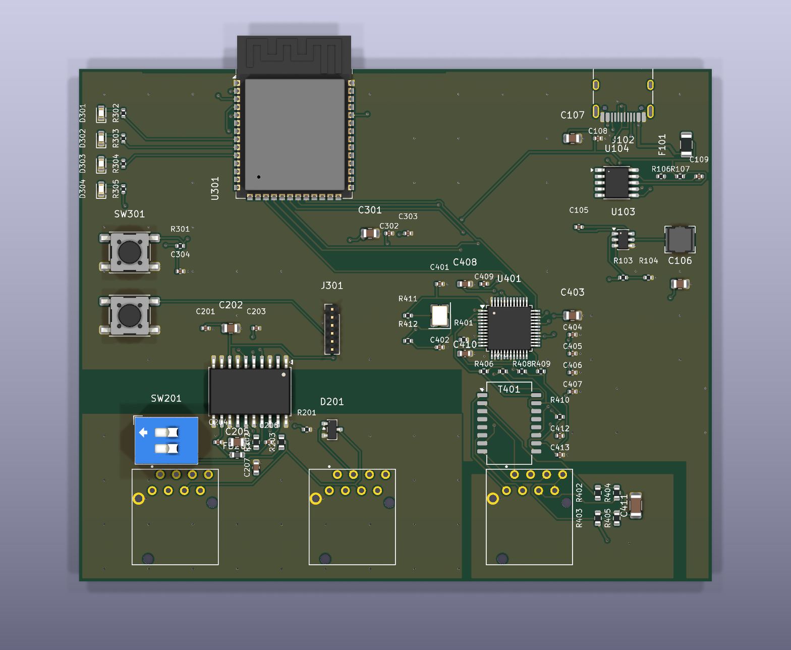
Top view render of the CANary rev A board, showing the processor module at the top, the network controller and magnetics on the right, the isolated CAN transceiver at lower left, and three connector footprints along the bottom edge
Component side. Power enters top right, the processor module is top centre, the network controller and its magnetics are on the right, and the isolated CAN section is the darker region at lower left.
BlockPartsWhat it does
PowerUSB-C PD → CH224K → AP63200One USB-C connector is the only power inlet and the only programming port. A CH224K negotiates the supply and an AP63200 buck drops it to 3.3 V. There is no barrel jack and no PoE on this revision.
ProcessorESP32-S3-WROOM-1-N8Dual core with 8 MB of flash, running ESP-IDF. Native USB, so the same cable carries power, firmware and the console. The module sits at the board edge with its antenna overhanging, so its keep-out falls off the board rather than eating copper.
NetworkW5500 over SPI, discrete magneticsA hardwired TCP/IP controller rather than the processor's own MAC, driven at 20 MHz. Magnetics are discrete parts feeding a Neutrik etherCON, so the network jack is the same locking connector as the rest of a touring rack.
CANADM3053, isolatedTransceiver, digital isolators and an isolated DC-DC in one part. It carries the bus at a fixed 100 kbit/s onto two more etherCON jacks, and it is the boundary between the two ground domains on this board.

100 × 81 mm, four layers, 76 placements and all of them on the top side, so the solder side is bare copper and the board can be assembled in one pass. Fifty lines on the bill of materials, forty-five of which carry a distributor part number that was checked against live stock rather than a catalogue.

The barrier down the middle

The single most important thing about this board is that it is two boards electrically. Everything on the network side shares one ground. Everything on the CAN side shares another. They are separated by seven millimetres of empty board with no copper crossing it, and the only things that span the gap are the isolator inside the ADM3053 and the transformer that feeds the far side its power.

This is not a refinement. An amplifier rack and the laptop running the control software are usually in different parts of a building, on different mains circuits, and the CAN bus is a long piece of copper joining them. Without isolation that bus becomes the lowest-resistance path between two earths, and the traffic on it is the least of the consequences.

It also has an awkward practical edge. A single ground clip across the barrier defeats it, and a board that has had one on it will pass every functional test in the procedure and still be ruined. The bring-up document opens with that warning rather than closing with it, and the probe drawings shade the isolated region so it is obvious which side a meter lead is on.

The case

The body is one printed piece: a rounded tube that prints standing on its rear end, so every layer is a closed ring and nothing needs support. The board slides in from the front on printed rails, and two flush end plates close it with eight M3 screws into heat-set inserts. The front plate takes the three etherCONs' own panel screws.

It prints in glass-filled ABS in about four and a half hours and 126 g on a 0.4 mm nozzle. A small white PLA insert lights the status LEDs through the lid, and a push-on cap covers the two service buttons. The rear plate steps in to meet the USB-C socket, which sits well inside the case because the antenna behind it needs the room. Everything is generated from one parametric script, and the repo carries the STEP and STL files and ready-sliced plates.

What board #1 has done

One board out of the batch, on one bench. Everything below is either something that was observed or something that was not attempted — there is no third category here.

  • USB enumeratedverified

    First plug-in, no button sequence. This was the biggest risk on the batch — these boards were made before the USB routing was tidied, and the connector is the only way to power them.

  • Flash and processorverified

    8 MB confirmed, chip revision read back, firmware written and verified.

  • Network controllerverified

    Answered its version register at both 4 MHz and the full 20 MHz the application runs at, and a write-then-read walk proved the bus in both directions.

  • CAN transceiververified

    A frame went out of the processor, across the isolation barrier, onto the bus wires and back, with no transmit or receive errors. That also proves the isolated supply started, which nothing on the other side of the barrier can observe.

  • Live networkverified

    Link in 2.2 seconds, DHCP lease taken, bridge listening.

  • Protocol, end to endverified

    A host-side acceptance script ran nineteen checks against the board over the network — discovery, the full command set, and the two commands that must go deliberately unanswered. All nineteen passed.

  • Discovered by the control applicationverified

    It appears in the interface list at its own address, with a green status.

  • USB network adapterverified

    Plugged into a Mac, the board shows up as a network adapter, hands the laptop an address without taking over its internet connection, and serves its settings page. The same nineteen checks pass down the USB cable.

  • CAN against a real busnot yet

    The transceiver has only ever talked to itself. Nothing has been connected to an amplifier.

  • Supply rails and isolation resistancenot yet

    Board #1 went straight to USB-C power, so the bench-supply sequence and the measurements that go with it were skipped.

  • Indicator LEDs and the power-delivery status pinnot yet

    Both need a person looking at the board rather than a script reading it.

  • Driving amplifiersnot yet

    The last link. The control application lists the board but has not been taken through to controlling anything with it.

What building it found

Faults that survived every simulation and test before them, and surfaced within hours of meeting real hardware. They are the argument for building the thing.

A stack overflow nothing else could reach

Typing the self-test command at the board's console crashed it every time. The command builds a two-kilobyte report on the calling task's stack, and the console task had four kilobytes to hold that plus two device drivers. The identical code passes at start-up, because start-up runs it on a larger stack — which is why several hundred automated checks, a full emulator boot and a simulated acceptance run had all gone green. Fixed.

A network adapter that never answered

The first time a laptop met the USB network build, it saw an active adapter, sent 166 packets and got none back. Four separate faults were stacked behind that, and every one of them reported success while doing nothing: the USB library never raised the "host connected" signal the code waited for, the address server was stopped by its own setup and never restarted, the settings page refused every visitor as foreign, and the board's advertised name was being read from memory that had already been freed — on the Ethernet build too. All four fixed, and proven on the board, the same afternoon.

The board describes its own socket wrongly

The control application finds the board and lists it, but under the wrong transport: two fields in the discovery record were set from a misreading of how the application decodes them. It was caught by reading the label the application displayed, then confirmed by standing a second emulated device beside the real one with the fields set differently. Not yet fixed.

How it gets tested

The board tests itself. A separate firmware image walks the hardware — flash size, network controller at both clock speeds, a bus write and read-back, the CAN loopback across the barrier — and prints a result line per check plus a machine-readable summary.

A host script does the network half. It runs the real discovery exchange and the full command set against the board, over the network jack or the USB cable, including the two commands that must produce no reply at all. A simulation mode runs the same checks against a software model, so the rig was proven before any board existed.

The bench procedure is written down. Every expected value is tagged with where it came from — a datasheet, a calculation, or a guess — so that when a measurement disagrees, you know whether to doubt the board or the document. The probe drawings are generated from the board file and refuse to build if a probe has moved off its pad.

The firmware's protocol code runs on a laptop too. It is kept free of the chip's SDK so the same C compiles on a host, where several hundred checks, an end-to-end run on real sockets and two fuzzers exercise it on every change.

Help wanted

Put one on a real amplifier bus

The next proof needs a rack of CAN-era d&b amplifiers, and the bench this was built on does not have one.

Everything up to the CAN wire is proven on a real board. What is left is the part only a real rig can answer: the control application driving an amplifier through CANary, over a bus of real length with real termination. If you have that rig, a built board or the parts to build one, a report of what happened — working or not — is the most useful contribution there is right now.

  • User guide

    Flashing, connecting it, wiring CAN, and reading the front-panel codes.

  • Bench bring-up

    The step-by-step procedure for a new board. Read §0 before powering one.

  • Building a board

    Fab outputs, the bill of materials, and the parts that are fitted by hand.

Open an issue Bench results, faults and questions all go here.

Where it goes next

The immediate work is finishing what board #1 started: correcting the discovery fields, taking the control application all the way through to driving an amplifier, and putting the CAN side on a real bus. After that, the rest of the batch and the measurements that were skipped.

Rev B already has a list: power over Ethernet, protection on the network jack, a pull-up on the network controller's reset line that the processor currently leaves floating until firmware runs, and a silkscreen pass.